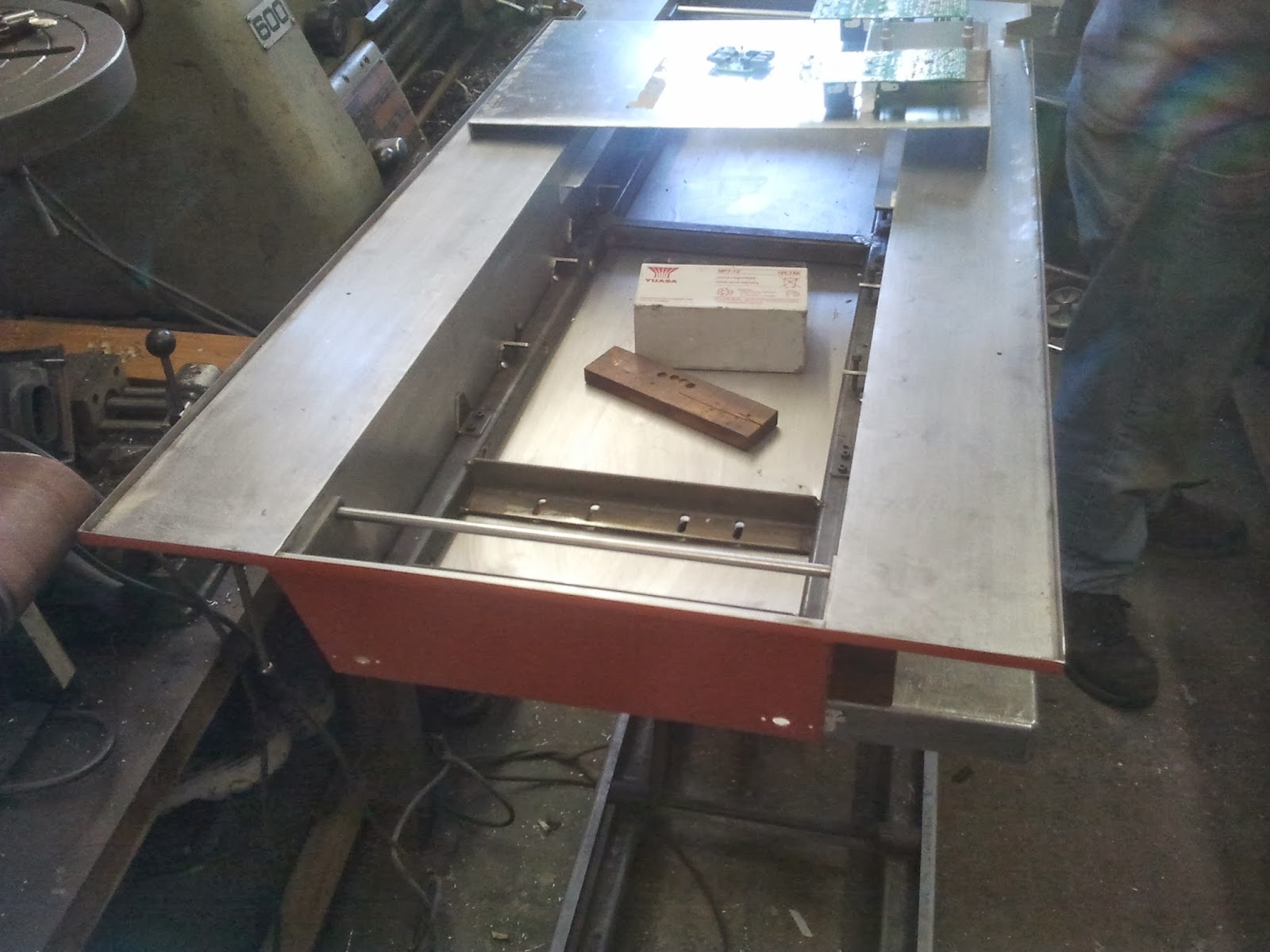
After a hiatus of some time dealing with the 'other' Big Panther and a couple of projects myself and Howard had promised to do, finaly some progress to my Big Panther :-)
Basicaly, all weekend has been taken up with fitting the running boards (Saturday) and making and fitting the front mud guards (Sunday). The running boards were made way back when last year but what with one thing and another that was as far as they got! Saturday was spent fitting these with the 'swastika' brackets (see previous post for explanation!) This wasnt as easy as it seems :-/
A bit wobbly to start with!! That'll be alright H :-)
Thats better.
A close up of one of the 'swastika' brackets. On the real thing the running board is bolted to the bracket with dome headed coach bolts and are quite shallow. Unfortunately, because you cant get a nut underneath the bracket (believe me, its impossible!) when we ground down the ordinary hex head bolts into a dome shape we had to keep the domes quite pronounced as we had to fit these with a pair of mole grips and thread lock so they are a bit bigger than they should be. Hopefully when its all painted they wont look quite so big...
H starts work knocking up the mud guards...
And here they are! These next few pics dont do them justice as you cant see the curved angle brackets underneath amongst other things :-) A very complicated job making them a; look right and b; fit! I had all sorts of dimensions from the real thing in Bovington Tank Museum but you might as well throw those out of the window (remember the fiasco with the rear tool boxes?) so we made these look right hence there are a few compromises!
A three quarter view showing the small hinged section (ignore the huge hinge pin, thats temporary!) and the small bracket that bolts to the chassis extension. These arent bolted into the chassis as you'd never get the top off (easily) so the bolt heads are just dummies and the bracket rests on the chassis. Note one of H's modified shackles in place to see how it all looks.
Here's a side three quarter view with the mudguard and running board. I think we've got it more or less right!!!
The superstructure top has now stayed at H's for further work while the chassis has come back with me as all further work on the top can be done without reference to the chassis. No work next weekend as Kaths car failed its MOT so I'll be working on another German tank next weekend!!
Sunday, 9 March 2014
Sunday, 12 January 2014
Challenger Chassis Pics
Not a new project by any means but the pictures have been posted to help a fellow Ch1 owner see how we got Lyndons Chally to run half sensibly!!
Wednesday, 22 May 2013
May Update
Been busy this month with our Big Yellow Truck getting it successfully through an MOT, giving it a spring clean in the back and doing some cleaning and painting of the chassis, With that and a weekend away there hasnt been much time for progress on the Big Panther. While I've been sidetracked however, Howard's been busy! Whats better than one Big Panther?
Yup, you guessed it, two Big Panthers!! Here's the second chassis behind my tank at the Uckfield Panzerwerks. I arrived Saturday morning with my tank to carry on working on it and found the almost completed second chassis :-)
Some close ups of the second chassis and one of the rear idler adjusters. All this needs painting which is something we hope to do soon and get it put together.
Meanwhile...we modified the bottom of the turret a little as it was rubbing on parts of the hull while traversing.
Well when I say we... :-)
The rest of the day was spent removing the moulded running boards and sanding off the moulded tool racks and details. Because the cutouts for the sponsons were wrong on the glacis, we cut back the glacis and trimmed the sides back. Not easy to explain but it makes the whole thing look that much better! Not seen in this shot but the brackets to support the front mudguards have been fitted as well.
Here Howard's making up the new running boards. Because they are nearly three feet long, Howards folder cant fold it all in one piece so they're made in three pieces Tig welded together. Then of course we realised that we needed to make the support brackets! I was dreading this as they are a complicated thing (typical German!)
This was the Mk1 version, made flat and the folded on a jig...
...to this. Nearly right but not quite! So after two other attempts...
...we came up with this, the Mk4 version!
This is just one of twelve (groan!). They'll need a little tidying up and the sloping fold on the far right is not prototypical, the real ones were welded but we cant weld to a fibre glass top so ours will be bolted on but thats about it!
Next weekend is the first show of the season and work will soon start painting and assembling the second chassis so work will probably slow down a bit on the first model. We shall see.
Yup, you guessed it, two Big Panthers!! Here's the second chassis behind my tank at the Uckfield Panzerwerks. I arrived Saturday morning with my tank to carry on working on it and found the almost completed second chassis :-)
Some close ups of the second chassis and one of the rear idler adjusters. All this needs painting which is something we hope to do soon and get it put together.
Meanwhile...we modified the bottom of the turret a little as it was rubbing on parts of the hull while traversing.
Well when I say we... :-)
The rest of the day was spent removing the moulded running boards and sanding off the moulded tool racks and details. Because the cutouts for the sponsons were wrong on the glacis, we cut back the glacis and trimmed the sides back. Not easy to explain but it makes the whole thing look that much better! Not seen in this shot but the brackets to support the front mudguards have been fitted as well.
Here Howard's making up the new running boards. Because they are nearly three feet long, Howards folder cant fold it all in one piece so they're made in three pieces Tig welded together. Then of course we realised that we needed to make the support brackets! I was dreading this as they are a complicated thing (typical German!)
This was the Mk1 version, made flat and the folded on a jig...
...to this. Nearly right but not quite! So after two other attempts...
...we came up with this, the Mk4 version!
This is just one of twelve (groan!). They'll need a little tidying up and the sloping fold on the far right is not prototypical, the real ones were welded but we cant weld to a fibre glass top so ours will be bolted on but thats about it!
Next weekend is the first show of the season and work will soon start painting and assembling the second chassis so work will probably slow down a bit on the first model. We shall see.
Tuesday, 30 April 2013
Late April Update
Some more progress :-) This time some pics of the turret work, the fabricated stowage boxes and the result of wielding my trusty soldering iron for some hours in the shed!
Firstly the turret pics.
The finished traverse assembly. The square base to the upright bolts to the tank chassis floor, the wires coming out of the upright are the turret power cables up to the integral three pin plug.
Looking directly down onto the underneath of the turret showing the angle iron base frame and the centre spigot support legs.
Same thing from a side view showing the elevation motor and recoil servo to the left.
Close up of the frame and one of the support rollers. This bears onto the top of the hull but is purely for balancing rather than taking any of the weight, that is taken by the traverse mechanism.
Close up of the elevation motor and recoil servo.
Close up of the centre spigot with the built in three pin turret power plug.
Next some pics of the rear stowage bins fabricated by Howard. These are superb and exactly to scale, however, they are too small for the rear panel so I'm not sure what we're going to do about that :-/ Not H's fault, I gave him the correct dimensions but the rear panel is not correct so they're about 20mm too short. Its so annoying as I'd wished I'd checked the rear panel measurements and adjusted the bins accordingly but cest la vie :-(
Superb.
Spot on.
Too short :-0
Next some short videos demonstrating some of the features of the working electrics.
First the synchronised exhaust smoke. Should have left it a bit longer to make more smoke but you get the idea. This uses the Benedini oil smoke module connected to the Benedini sound module but just to run the fans.
Couldnt get the short video showing the idler adjusting so here's the link to the YouTube appearance.
Idler Adjustment Video
Note how slow the idler moves and the led lighting when the limit switch has cut power to the motor.
This shows what happens inside when the idler is moving on the outside. Also shows the limit switches cutting power to the motor and putting the lighting the led on the control panel.
And to prove the turret works ok! We think the belt needs tightening as when the turret is sitting on the hull it tends to catch a bit as it rotates making it bounce too and fro.
Wont get much done this weekend as we've got some work to do on our tank transporting truck. More as and when.
Firstly the turret pics.
The finished traverse assembly. The square base to the upright bolts to the tank chassis floor, the wires coming out of the upright are the turret power cables up to the integral three pin plug.
Looking directly down onto the underneath of the turret showing the angle iron base frame and the centre spigot support legs.
Same thing from a side view showing the elevation motor and recoil servo to the left.
Close up of the frame and one of the support rollers. This bears onto the top of the hull but is purely for balancing rather than taking any of the weight, that is taken by the traverse mechanism.
Close up of the elevation motor and recoil servo.
Close up of the centre spigot with the built in three pin turret power plug.
Next some pics of the rear stowage bins fabricated by Howard. These are superb and exactly to scale, however, they are too small for the rear panel so I'm not sure what we're going to do about that :-/ Not H's fault, I gave him the correct dimensions but the rear panel is not correct so they're about 20mm too short. Its so annoying as I'd wished I'd checked the rear panel measurements and adjusted the bins accordingly but cest la vie :-(
Superb.
Spot on.
Too short :-0
Next some short videos demonstrating some of the features of the working electrics.
Couldnt get the short video showing the idler adjusting so here's the link to the YouTube appearance.
Idler Adjustment Video
Note how slow the idler moves and the led lighting when the limit switch has cut power to the motor.
This shows what happens inside when the idler is moving on the outside. Also shows the limit switches cutting power to the motor and putting the lighting the led on the control panel.
And to prove the turret works ok! We think the belt needs tightening as when the turret is sitting on the hull it tends to catch a bit as it rotates making it bounce too and fro.
Wont get much done this weekend as we've got some work to do on our tank transporting truck. More as and when.
Tuesday, 9 April 2013
Early April Update
Well, after a couple of weekends living it up and doing family stuff we finaly have some progress!
Howard has made the turret support frame which incorporates the recoil mechanism mounted on the stout plate seen in the previous post. Last weekend I took the chassis over to Uckfield (still on the temporary electrics) for the trial fitting of the turret. Once again, things didnt work out quite to plan and poor Howard was seen to be giving me 'that look' again! Not going into detail but we have measured the hull top and turret and confirmed they are more or less right with the correct angles as well when we first got the model. So why the bloody hell doesnt it fit together correctly? lol We had decided where the turret pivot point was but when we mounted the turret it was found to be too far back and overlapped the engine hatch. This would have prohibited access to the switches and controls as well as looking wrong of course. Howard did some metal working jiggery pokery and lo and behold the turret rear sat just in front of the engine hatch, but..... the mantlet was far too far forward and stopped the drivers and radio ops hatches opening!!! We looked, we measured, we mused and we argued but eventually we worked it out, the curved turret front just behind the mantlet was too far forward. So... we cut it off, cut it down and hot glued it back on just to try it out and voila, success! Again, doesnt sound like much but that took most of the day :-( We also made a start on the flamvernichter exhausts, made from rainwater down pipe and 90 degree bends. Anyway, here's some pics.
A view of the turret from the front. Note the mantlet's upside down! Not easy to see in this picture but the gun barrel is removable with one of Howards bayonet fittings.
A rear view showing the disputed replacement rear sides!
Underneath the turret you can see the finished frame nicely filled and blended into the base of the sides. The turret is mounted on the traverse mechanism and this is held in the vice. To the left of the pulley is the elevation motor and above the stub of the gun barrel is the recoil arm.
The engine hatch doing what it was designed for, holding the top in place.
Now the turret sits about right, just in front of the engine hatch...
...and behind the hatch panel.
The turret mechanism mounted on its 30mm square tube post and viewed through the turret ring.
The front of the turret with the mantlet removed to enable the curved front of the turret to be modified. You can see the trunnions for the gun barrel pivot and the barrel outer to allow the barrel to recoil.
The view from above through the engine hatch showing the controls beneath.
A close up of the turret traverse mechanism showing the three pin XLR connector built into the central spigot. This cleverly enables the electrical connection to be made and disconnected automaticaly when the turret is placed or removed from the tank.
The start of the flamvernichters! A lot more work to be done but a good start :-)
Hopefully more next weekend.
Howard has made the turret support frame which incorporates the recoil mechanism mounted on the stout plate seen in the previous post. Last weekend I took the chassis over to Uckfield (still on the temporary electrics) for the trial fitting of the turret. Once again, things didnt work out quite to plan and poor Howard was seen to be giving me 'that look' again! Not going into detail but we have measured the hull top and turret and confirmed they are more or less right with the correct angles as well when we first got the model. So why the bloody hell doesnt it fit together correctly? lol We had decided where the turret pivot point was but when we mounted the turret it was found to be too far back and overlapped the engine hatch. This would have prohibited access to the switches and controls as well as looking wrong of course. Howard did some metal working jiggery pokery and lo and behold the turret rear sat just in front of the engine hatch, but..... the mantlet was far too far forward and stopped the drivers and radio ops hatches opening!!! We looked, we measured, we mused and we argued but eventually we worked it out, the curved turret front just behind the mantlet was too far forward. So... we cut it off, cut it down and hot glued it back on just to try it out and voila, success! Again, doesnt sound like much but that took most of the day :-( We also made a start on the flamvernichter exhausts, made from rainwater down pipe and 90 degree bends. Anyway, here's some pics.
A view of the turret from the front. Note the mantlet's upside down! Not easy to see in this picture but the gun barrel is removable with one of Howards bayonet fittings.
A rear view showing the disputed replacement rear sides!
Underneath the turret you can see the finished frame nicely filled and blended into the base of the sides. The turret is mounted on the traverse mechanism and this is held in the vice. To the left of the pulley is the elevation motor and above the stub of the gun barrel is the recoil arm.
The engine hatch doing what it was designed for, holding the top in place.
Now the turret sits about right, just in front of the engine hatch...
...and behind the hatch panel.
The turret mechanism mounted on its 30mm square tube post and viewed through the turret ring.
The front of the turret with the mantlet removed to enable the curved front of the turret to be modified. You can see the trunnions for the gun barrel pivot and the barrel outer to allow the barrel to recoil.
The view from above through the engine hatch showing the controls beneath.
A close up of the turret traverse mechanism showing the three pin XLR connector built into the central spigot. This cleverly enables the electrical connection to be made and disconnected automaticaly when the turret is placed or removed from the tank.
The start of the flamvernichters! A lot more work to be done but a good start :-)
Hopefully more next weekend.
Subscribe to:
Posts (Atom)