Progress has been slow but steady on the Big Panther. Last weekend I was working on the electrics panel, while Howard made some modified spring assemblies and springs then we both made a start on the turret.
This weekend has been all about the turret! Yesterday (Saturday) Howard made the turret traverse mechanism which incorporates an electrical connection which is automatically made when the turret is mounted. This is something I thought about while watching others struggling with their 1/4 scale turrets and umbilical cables but H turned my thoughts into reality (as usual!). Today (Sunday) we made the replacement rear sides and fitted them. We had to do this twice as the first time it didnt go to plan. I think they're about right now but that was using the Mk1 Eyeball rather than relying on measurements which were proven to be pants!!! If in the future you see these parts and think they are wrong, take my advice, keep your thoughts to yourself as if Howard doesnt sock you I might!!! LOL.
Anyway, after this, a start was made on the internal space frame for the turret. This will have hardpoints for the gun trunnions, electrics, speakers and dolly. This will be next weeks job now.
In the background I have been spending money like water :-( One order to 4QD for the speed controllers and Interfaces for mine and A.N.Others tank and we were £660 lighter! Add up other bits and bobs and the electrics becomes expensive. All neccesary stuff though unfortunately. I hope to progress with the electrics panel during the week and when I have something to show I'll get some pictures of that and post them.
This is how the turret looked when we started hacking it about!
Although the rear sides were at the correct angles with respect to the sides and rear they were too short.
So after a lot of measurement and more application of Eyeball Mk1 the cuts were made.
Also while we were about it, the mantlet and curved front for the turret were removed so that new locating points could be made attached to the turret spaceframe.
Here's an example of one of the front wheelstations modified spring assemblies. The triangular metal plate bolts the the chassis frame tube and the yoke to the left engages with the swing arm. We found that the springs could move on the first swing arms and the first drive chain would run across the coil springs making a juddering noise, the longer tube welded to the triangular plate brings the spring well away from the motor and chain.
This is the start of the turret traverse mechanism. The pulley is attached to a large tube which sits in the blue bearing housing. This all sits in the hull of the tank. In the middle is the start of the turret, which for now is just a steel tube...
...with a keyway for locating and an electrical plug and socket within. The plug is arranged (not in this pic) so that the steel tube and keyway engages first within the pulley tube before it makes contact with the socket. This should ensure the reliability of the plug and socket and prevent them getting bent or broken.
Howard Tig welds the motor mounting bracket...
...et voila the finished article. The spigott out the bottom of the bearing block will fit in the 30mm square tube of the turret mount (remember in one of the previous chassis pics a tube sticking up from the middle of the hull? That will be cut to length and this assembly affixed to it!)
Here's a short video to show the mechanism working. This is a 24v motor working on a 15V power supply so the mechanism has the potential to spin a bit faster if need be!
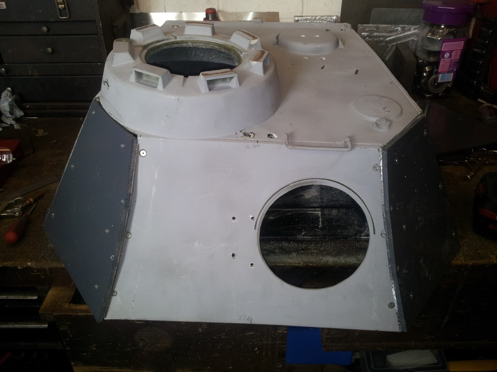
These are the Mk1 sides before cutting...
...and these are the Mk2 sides after cutting. I'm happy with these although it was a bone of contention: see above note!!!
This is the start of the turret spaceframe looking towards the front of the turret. This will have mounting points for gun trunnions, electrics, speakers and dolly. Obviously it will support the traverse spiggot which plugs into the traverse mechanism as well.
Hopefully by next weekend we'll see some progress on the electrics panel and I can show you the layout of this. Onwards and upwards :-)