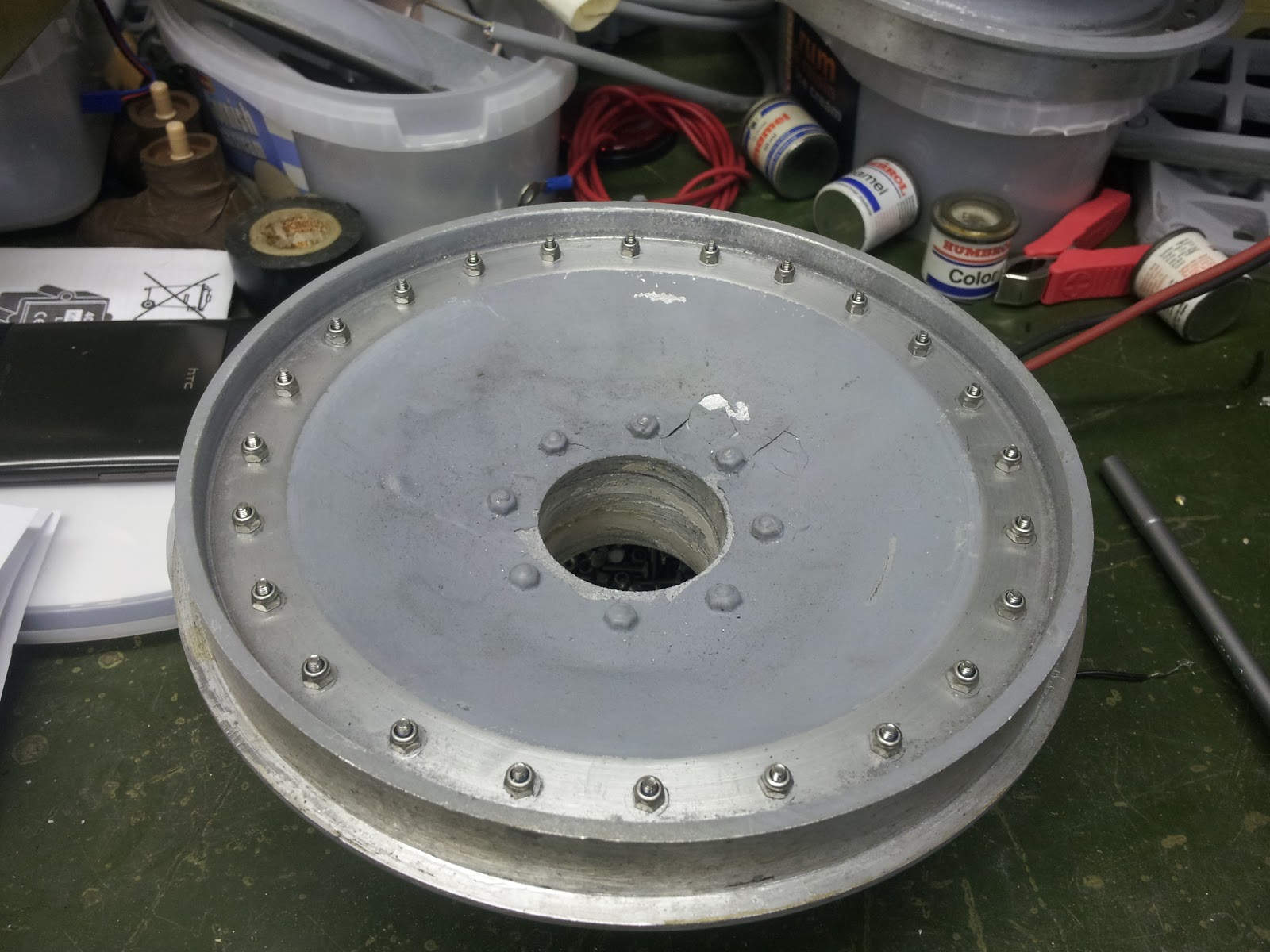
Finished all the wheels today (Sunday). We made some steel rings up to represent the step in the back of the wheels, seen on this real wheel,
unfortunately, the way that the wheels have been made, the flat section towards the rim is wider than it should be as in this picture,
so we made the disc wider than it should be otherwise it would have looked silly the correct width, if you see what I mean! Anyway, below is a picture of a ring inset in the wheel,
and below with all the nuts and bolts fitted and the centre reprofiled and bolts fitted.
Once its got some paint on it, it should look about right. There are some limits with all this re-manufacturing and compromises to be made but hopefully the whole effect will be alright!
Next we've got the wheel caps to modify with seperate bolt heads so we can fit tab washers behind them and to flatten the domed centre which on the supplied caps is to prominent. Watch this space.
Sunday, 21 October 2012
Thursday, 18 October 2012
Bolts (sigh!)
Got the nuts and bolts and fitted them into four wheels before I nearly lost my sanity!!! They look about right but unfortunately the bolts are a smidge too long. Call for the Dremel! And no, I'm not fitting those funny tab washer thingies behind the bolt head, I flatly refuse :-)
I'll grind the bolts down a smidge and bung a bit of paint on them to see what they look like.
Monday, 15 October 2012
Wheels This Weekend!
Very boring work this weekend! For some reason only known to themselves, the Russians didnt cast the roadwheels with sixteen bolts (ie the earlier version) or 24 bolts (the later version), no, they put 18 bolts!!! Where they got that from I dont know but the fact remains that it aint right. So.....poor Howard spent all day last Saturday knocking the cast bolt heads off on the lathe, then he made a template to sit in the wheel inside the rim for me to drill the new holes and that took all day as well :-( We have 700 nuts and bolts on order so guess who's got the job of fitting all them? :-/
Howard making the template on the mill using a rotary table to get the even steps between the holes.
The template clamped inside a roadwheel...
...and 24 nice little 2.5mm holes drilled in one of the wheels. Multiply this by 24 wheels (we didnt bother with the inside of the double wheels as you wont see them) explains why it took all day and why I needed a beer by the evening :-)
Howard making the template on the mill using a rotary table to get the even steps between the holes.
The template clamped inside a roadwheel...
...and 24 nice little 2.5mm holes drilled in one of the wheels. Multiply this by 24 wheels (we didnt bother with the inside of the double wheels as you wont see them) explains why it took all day and why I needed a beer by the evening :-)
Sunday, 23 September 2012
Sprockets-Again!
Yet more work on the sprockets this weekend (well Friday!). Both inner rings have their bolts fitted and grooves needed to represent the two peices of the ring.
In hindsight, I think the bolt heads could have done with being a little smaller but they looked ok when we offered them up!
The outer rings have had the tab washer star shape made. I'm not sure if on the real things, they butt up against the centre cap or are clamped behind the cap but for the model its easier to make them all in one peice like this and then fit the cap over the top.
Here's a picture of Rex Cadmans Panther sprocket which has the centre cap missing which shows the individual locking tabs. The tabs at the 12 o'clock and 2 o'clock position look like they've been clamped as they have a different colour strip along the bottom which looks cleaner than the rest.
Besides which, the centre cap fits right up to the base of the base of the spokes, like this picture of the Bovington Panther, so it must overlap.
Anyway, here's a couple of pics of the tab washer spacer representation.
In hindsight, I think the bolt heads could have done with being a little smaller but they looked ok when we offered them up!
The outer rings have had the tab washer star shape made. I'm not sure if on the real things, they butt up against the centre cap or are clamped behind the cap but for the model its easier to make them all in one peice like this and then fit the cap over the top.
Here's a picture of Rex Cadmans Panther sprocket which has the centre cap missing which shows the individual locking tabs. The tabs at the 12 o'clock and 2 o'clock position look like they've been clamped as they have a different colour strip along the bottom which looks cleaner than the rest.
Besides which, the centre cap fits right up to the base of the base of the spokes, like this picture of the Bovington Panther, so it must overlap.
Anyway, here's a couple of pics of the tab washer spacer representation.
The six bolts will have their heads sanded flat to get rid of the modern markings. Also, the holes for the nuts around the edge of the sprocket ring have been drilled out to accept the 3mm nylok nuts suitably cut with three slots to look like a castle nut!
Here's the jig that Howard made up for sawing the bolts, all 64 of them with a junior hacksaw!!! Not a job I shall relish doing again :-/
There wont be much done now for a couple of weeks as Howard is working next weekend and we're both away the week after so dont look for any updates for a couple of weeks :-(
Monday, 17 September 2012
Last Weekend!
Last weekend was mainly about sprockets! H has made new spacers between the sprocket rings as I want to make a dummy cone shape to fit between the rings to represent the casting of the sprocket assembly. These new spacers are thick tubes so the bolts fit into threaded holes in the tube. As it has no flange, a dummy cone shape can be made out of nylon and slid over the tube. The inner ring has a split collar bolted to it which incorporates a keyway. The keyway stops it turning and the clamp bolt allows a little side to side adjustment!
With a Coke can for scale, heres a finished sprocket showing the split collar arrangement with its keyway and below a close up.
And the next three pictures show the two sprockets mounted on the gearbox assembly, again with the coke can for scale. You can start to see the size of the thing now!
Apart from the sprocket rings, chain and chain sprockets, Howards made all this from scratch! Worth his weight in curry's now (especialy as he's not so heavy now!).
We were looking at what nuts to use around the sprocket ring and have decided on three mm nylok nuts as they look the part. I have tried cutting them with slots to make them look like castle nuts which they should be but this wasnt very successful so plain old nuts they'll be, unless anybody's got any ideas???
More, as they say, as and when. Hopefully some work on the wheels next weekend :-)
With a Coke can for scale, heres a finished sprocket showing the split collar arrangement with its keyway and below a close up.
And the next three pictures show the two sprockets mounted on the gearbox assembly, again with the coke can for scale. You can start to see the size of the thing now!
Apart from the sprocket rings, chain and chain sprockets, Howards made all this from scratch! Worth his weight in curry's now (especialy as he's not so heavy now!).
We were looking at what nuts to use around the sprocket ring and have decided on three mm nylok nuts as they look the part. I have tried cutting them with slots to make them look like castle nuts which they should be but this wasnt very successful so plain old nuts they'll be, unless anybody's got any ideas???
More, as they say, as and when. Hopefully some work on the wheels next weekend :-)
Sunday, 9 September 2012
This weekend!
Slow progress as there's a lot of headscratching with where we are now. I dont know how Howard would have managed without me (making the tea!!). Anyway, more progress of the idler adjustment arrangement with a small video showing it working. Whether it'll be man enough, we wont know until we put it all together but its strong enough when you try and grab hold of it to try and stop it! Because of this we're going to fit some limit switches at the end of each sides travel.
This picture will help it all make sense with an idler mounted on one of the shafts. Again, the slope of the plate towards the left represents the sloping rear panel and the motor will be hidden away inside the hull.
Below is how the idlers looked originaly, with the outer cap all part of the casting. This is because the original is glued on to the bearings and then these are glued on the shaft! Not on my model they're not!! So...Howard machined the cast cap off as in the pic above...
... made an insert to fix the new cap too and to retain the outer bearing...
and made a new cap which fits a treat. The idler will be held on by circlips on the shaft, the inner accessable and the outer behind this cap so you can remove the idler easily. This modification to the idlers and making the caps took all of our Sunday and an hour or so yesterday afternoon, thats what I mean by time consuming :-/
More as and when.
This picture will help it all make sense with an idler mounted on one of the shafts. Again, the slope of the plate towards the left represents the sloping rear panel and the motor will be hidden away inside the hull.
Below is how the idlers looked originaly, with the outer cap all part of the casting. This is because the original is glued on to the bearings and then these are glued on the shaft! Not on my model they're not!! So...Howard machined the cast cap off as in the pic above...
... made an insert to fix the new cap too and to retain the outer bearing...
and made a new cap which fits a treat. The idler will be held on by circlips on the shaft, the inner accessable and the outer behind this cap so you can remove the idler easily. This modification to the idlers and making the caps took all of our Sunday and an hour or so yesterday afternoon, thats what I mean by time consuming :-/
More as and when.
Saturday, 8 September 2012
Friday 7th Sept
Howards been a busy bee while I've been away enjoying myself! He's cracked on with the two 30mm square tube main frames which incorporate the swing arm bushes and suspension mounts.
Its a little difficult to see here with all the other clutter but its clamped in the vice and pointing to the left!
Here's a close up of one of the suspension components. Using threaded rod (sleeved to prevent that awful twanging noise that you sometimes get with coil springs) each position is independantly adjustable as we wont know how the finished model will sit/ride until its done!
Excuse the smoke but H was having a fag break! This is a view of the other side of the main chassis rail with the swing arms prevalent. Of course, these will have axles fitted for the wheels to sit on.
Here's the right hand adjustable idler assembley. The idler arm as you can see is fairly chunky :-) Everything is keyed to to prevent the assembley slipping. The angled plate behind will be welded to the end of the above main frames and the sloping angle to the left is the rear panel (where the exhausts sit!).
All will become clear when all these assembleys are fitted to the main frame/frames but Howard is relcutant to do this until all the he's happy with it all as when it goes together it will be awkward to work round it all because of its size!
Today (Saturday 8th) we (yes, I know, the Royal we!) are concentrating on mounting the motors to the adjustment mechanisms. Hopefully some more pictures today or tommorow :-)
Its a little difficult to see here with all the other clutter but its clamped in the vice and pointing to the left!
Here's a close up of one of the suspension components. Using threaded rod (sleeved to prevent that awful twanging noise that you sometimes get with coil springs) each position is independantly adjustable as we wont know how the finished model will sit/ride until its done!
Excuse the smoke but H was having a fag break! This is a view of the other side of the main chassis rail with the swing arms prevalent. Of course, these will have axles fitted for the wheels to sit on.
Here's the right hand adjustable idler assembley. The idler arm as you can see is fairly chunky :-) Everything is keyed to to prevent the assembley slipping. The angled plate behind will be welded to the end of the above main frames and the sloping angle to the left is the rear panel (where the exhausts sit!).
This is the other side of the above...
...and here it is with the adjustment mechanism fitted. The threaded rod turns mounted in its brass sleeves in the two horizontal bearers which draws the brass threaded boss too and fro in the funny shaped square block seen clearer in the above pic.All will become clear when all these assembleys are fitted to the main frame/frames but Howard is relcutant to do this until all the he's happy with it all as when it goes together it will be awkward to work round it all because of its size!
Today (Saturday 8th) we (yes, I know, the Royal we!) are concentrating on mounting the motors to the adjustment mechanisms. Hopefully some more pictures today or tommorow :-)
Subscribe to:
Posts (Atom)